
History
In previous years, our team has made several efforts at data acquisition on the boat. Our telemetry system for the 2017 Solar Splash competition consisted of a Raspberry Pi connected to several sensors in the boat, including an Arduino which read battery voltage and GPS coordinates. This system collected and displayed data on the boat using a miniature LCD display embedded in the dashboard. This screen was delicate, and several of the displays broke.
Another drawback of previous systems was the difficulty of wiring sensors; because sensor data is being collected from numerous locations on the boat using several types of sensors, wiring would become difficult and disorganized. Following these setbacks, our team switched focus to other aspects of the boat design and did not have time to complete the telemetry system and use it during competition. After competition and the decision to move to a different boat hull, we were unable to easily reuse this system.
Analysis of Design Concepts
Our team decided it was a priority to implement a proper telemetry system because data collection would improve our performance in all areas. After discussing the difficulties of creating a telemetry system in previous years, we concluded that our challenges stemmed from a lack of planning and purpose behind the telemetry system. We started by deciding the requirements for the telemetry system.
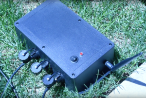
The completed telemetry server in use during field testing.
The telemetry system needed to include several components: A telemetry communication network, a central server on the boat to aggregate all data, a wireless connection which could send data to a computer on the shore, and software to interpret and display the data. Additionally, the entire telemetry system needed to be self-contained and modular, to fit in with our overall design philosophy for this year; to accomplish this, early in the design process we chose an enclosure that was consistent with other boat systems.
Communication Network
Our team evaluated several options for the telemetry communication system, including the use of a LAN network, a CAN Bus system, and a USB-Serial based system. After evaluating the options, we decided to use a system of USB-serial connections. We chose this method because all of our sensors would be outputting serial data. We could use a USB hub to open serial connections with up to 14 devices, restricted by the Raspberry Pi’s power limitations.
As a side-effect of the use of a powered USB hub in the telemetry system, the telemetry box powers all the devices connected to it via the auxiliary battery. This means that our individual sensors do not require their own separate power supply, simplifying the wiring greatly in the boat.
An additional benefit of the USB system is that it uses entirely off-the-shelf electronics parts; the USB hub, auxiliary battery, and USB cables are all readily available and extremely cheap so our telemetry system can be expanded trivially.
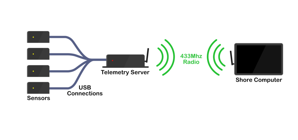
The Telemetry network design used in the 2018 boat.
Sensors
We decided that each of the sensors in the telemetry system would be an Arduino or similar microcontroller, running a program to collect data and output it to the network. Each separate sensor position in the boat would have a different microcontroller to read its data. This design is advantageous compared to a central microcontroller with many sensors because when coupled with a well-designed communication network the strategy increases modularity and reduces the number of wires in the boat.
The data to be collected is as follows:
- Motor Controller Throttle Value
- Motor Controller Temperature
- Motor Shaft RPM
- Battery System Voltage
- Battery System Amperage Drawn
Each data point is collected by a microcontroller which outputs the data directly into its serial stream.
Telemetry Server
The telemetry system requires a central server which connects to all the devices on the network, aggregates all the data, and sends it to a display or to the shore computer. The current system consists of a Raspberry Pi 3, which is connected to a powered USB hub that forms the center of the telemetry network.
The software on the Raspberry Pi continuously scans all USB ports for new devices and starts a USB-Serial session with each device. The software parses all input serial data and forwards it over radio to the shore.
Wireless Connection
Once the telemetry server filters and aggregates the data received from the several USB inputs, it is necessary to relay this information to the shore to evaluate the performance of the boat. This is used during testing, where our team collects data extensively, and during competition where the team will use the data to instruct the skipper on boat speed.
A laptop running telemetry software and the telemetry box on the boat are connected over a 433Mhz radio antenna which sends serial data. This antenna has a range of approximately 1 mile, meaning when the boat is on the water the team members supporting from the shore can easily analyze the data and see the performance. This system consists of two boards: On one end, a USB interface with an antenna, and on the other, an antenna board with serial inputs. When power is applied to both boards, they automatically connect and begin transmitting data. The USB interface appears as a USB serial device which can be monitored in software. This solution was extremely simple and reliable, requiring very little setup and working natively with the Raspberry Pi’s serial output GPIO ports. The team already owned this radio system from unrelated projects, and while datasheets were unavailable for the exact model radio telemetry kit we were able to figure out the operation based on previous experience and other kits.
Diagram of the telemetry system; The individual sensors connect to the telemetry server using USB cables, and the telemetry server relays the data to the shore using a radio connection.
Telemetry Software
To display the data on the shore computer, we created a telemetry software in Python. This software automatically connects to the USB radio antenna using the pySerial library, and receives and processes all data that is relayed through the connection. The software contains an interface with several panels that display the data for the team’s usage, including:
- A raw log of all incoming telemetry commands
- A graph view which plots system voltage and amperage draw over time for using in endurance
- Status indicators for the important metrics including amperage and throttle
Design Testing and Evaluation
This telemetry system has proven to be effective: Our team has used the output data extensively during testing of individual subsystems and on-the-water testing. Because of the modular nature of the telemetry system, it is easy to use the system to relay any data output from an Arduino. Additionally, the system is compatible with the serial data that is output from the battery box, giving our team a complete view of the boat system. The addition of the ship-to-shore radio communication system means the skipper no longer needs to manually relay numbers to the members on the shore, allowing them to spend time driving while team members on the shore monitor their speed and power drain and advise them on driving technique.
One of these testing sessions, in this case done on-shore, is shown in the following video: